THE INFAMOUS SINGING MASKS
Fun with talking telephones - Part 2
Building your own transmogrifier
by Mad Martian®
The Transmogrifier
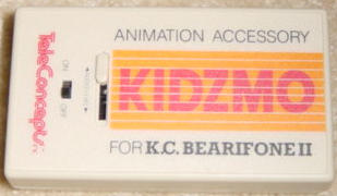
This device converts standard audio signals for use with talking telephones. While it is made for the KC Beariphone II, it can be used with any talking telephone as its purpose is to simulate communication over the phone line. If you can't find the commercial unit, called the "Kidzmo", you'll have to do some soldering. It's fairly easy and all the parts can be found at Radio Shack.
|
|
|
The commercial unit.
|
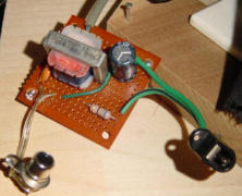
The home-built unit.
|
Additional features of the Kidzmo over the home-built unit:
1. Separate Mic and Line inputs.
2. Sensitivity adjustment (on the home built unit you will have to adjust the volume of your source to achieve the proper sensitivity).
Both units can run on a 9 volt DC power supply (center positive) commonly supplied with most answer machines. You can use a power y-adapter to run the phone and transmogrifier off the same power supply, minimum 500 miliamps. You can likely get by with the 400 ma power supply that comes with the phone to power both the phone and transmogrifier, but if you have to buy a power supply anyway, get a 500 ma.
Building Your Own Transmogrifier
The unit is fairly simple and only requires a few parts and solder joints. Cost will be about $20.
Parts List:
- Electrolytic Capacitor, 100uF, 9v or greater (Radio Shack #272-1028 or #272-1016)
- Ceramic Capacitor, .1uf (marked 104) (Radio Shack #272-135)
- 1/2 watt 68ohm resister (blue-gray-black-gold) (Radio Shack #271-1106)
- Audio Transformer (Radio Shack #273-1380)
- Power jack (size M) (Radio Shack #274-1582)
- RCA audio jack (female) (Radio Shack #274-346 or #274-852 gold plated)
- Phone cord of desired length (length depends on where you wish to place the transmogrifier in relation to the phone)
- wire for connections
- 9v center positive Power Adapter (500ma or higher)(best to get one from GoodWill or electronics surplus store, or Radio Shack part #273-1768 AND #273-1716)
- Heavy Duty 9v Battery Clip (optional, Radio Shack #270-324)
- SPST On/off switch with power LED (Radio Shack #275-018 or other)
- Project Box
Instead of the battery clip, I opted for a 9 volt battery compartment available from Mouser Electronics (part #122-BX0023) as this allows me to replace the battery without removing any screws. Mouser will have the rest of the components as well if you prefer to order everything over the web.
Solder Connections:
- Electrolytic (+) to Resistor (1) to Transformer (white) to Transformer (green)
- Disc Capacitor (2) to Transformer (blue)
- Telephone (red) to Transformer (red)
- * Audio (center) to Disc Capacitor (1)
- * Power Connector (shield) to Electrolytic (-) to Telephone (green) to Audio (shield) to Switch (LED)
- * Power (center) to switch (supply) to battery (red)
- * Power (switch) to battery (black)
- * Switch (load) to Resistor (2)
* when soldering parts that will be mounted to your project box, be careful not to solder wires that will need to go through holes in the box until after you put them through the holes. I suggest using a breadboard first (Radio Shack #276-003) by soldering wires onto these components. Then when you assemble the project in your project box, just solder the wire ends together as needed. Another trick is to cut slots in the project box instead of drilling holes. That way you can completely remove your project from the box without separating any wires (though it doesn't look as nice).
Making a Power Y-Adapter
You can find these on Amazon or make them yourself.
Parts List:
- Size M Coaxial DC Power Plug (male) (Radio Shack #274-1569 pack of 2)
- Size M Coaxial DC Power Plug (female) (Radio Shack #274-1577)
- 2-conductor cable (such as Radio Shack #278-1509). Be sure the cable has markings or coloring to be able to easily tell one conductor from the other. Thin speaker cable works fine. Shielded audio cable does not.
Solder Connections:
- Cut 2 equal lengths of 2-conductor cable.
- Solder 1 cable to each male connector. Be sure to use the same orientation: the gold-colored wire to the center and the silver-colored wire to the shield.
- * Solder the other end of both gold-colored wires to the female center.
- * Solder both ends of the silver-colored wire to the female shield.
* Be sure the plastic covers are in place before you connect the wires!
This will work great for using one power supply for two devices. Be careful never to exceed the power draw listed on the power supply. If the power supply gets hot to the touch (warm is normal), you are drawing too much power and need a supply with a higher amperage rating.
Copyright © 1995-2018 Mad Martian® All Rights Reserved.
